Reduction Gears Work: Unlocking Gearsets and Gear Ratio
The devil is in the details, and that couldn’t be more accurate than in the intricate world of reduction gears. So, how does reduction gears work? Join us on a journey through the complexities of gearsets and gear ratios, and gain a newfound understanding and appreciation of these mechanical marvels.
Key Takeaways
- Reduction gears play a crucial role in decreasing speed and increasing torque in mechanical systems.
- Gear ratio determines the force transferred between gears and can be adjusted by the arrangement of gears in gearsets.
- Different types of reduction gears, such as spur gears and planetary gears, are used in various applications ranging from wind turbines to automatic transmissions.
- Selecting the appropriate material and design for reduction gears is essential for longevity, efficiency, and resistance to operational stress and environmental conditions.
Introduction to Reduction Gears
Reduction gears are the unsung heroes behind every machine, every mechanism, turning the wheels of innovation. These essential components are used to decrease speed and increase torque in mechanical systems.
At its core, the introduction to reduction gears revolves around the concept of gear ratio, one of the core principles that govern their operation. The gear ratio is the relationship between the number of teeth on two meshed gears. This ratio determines the force that can be transferred from one gear to another, and consequently, the speed and torque. The larger the gear ratio, the more torque, but the slower the output speed.
Gearsets are a set of gears arranged to achieve a particular gear ratio. In connection with reduction drives, ‘gear can be used’ particularly, gearsets play a key role in achieving the desired balance of speed and high torque.
Reduction gears, often operating on a single axis, are fundamental to various applications from simple mechanisms like bicycle gears to complex systems in industrial machinery and automobiles. Their ability to influence speed and torque makes them an indispensable asset in our quest for technological advancement.
Components and Mechanics of Reduction Gears
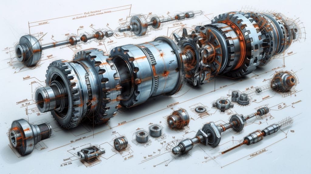
The fundamental components of a reduction gear, also known as a reducer, include the input shaft, output shaft, and the gearbox. The input shaft is connected to the motor, and the output shaft is linked to the load. The gearbox houses the gearsets, including the small gear and large gear, which are integral to the gear reduction process where reduction is required.
The reduction ratio, which is the ratio of the input speed to the output speed, is determined by the number of teeth on the gears. The gearbox contains two gears: the driver (input gear) and the driven (output gear). The driver gear, attached to the motor’s input shaft, transfers the motor’s energy to the driven gear on the output shaft. The output gear has more teeth than the driver gear, resulting in a reduction in output speed, but an increase in torque.
The motor propels the input shaft and the driver gear. As the motor spins the input shaft, the driver gear rotates, turning the driven gear at a slower rate due to the difference in teeth. This reduction in speed with a concurrent increase in force is the key function of reduction gears.
Understanding the mechanics of reduction gears offers ample scope for innovation, whether it’s refining existing applications or discovering new ones.
How Reduction Gears Generate Torque
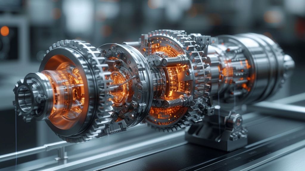
When reduction gears work, they operate on a principle known as torque multiplication. This principle is the driving factor behind how a smaller gear, spinning quickly, can generate greater torque when connected to a larger gear spinning more slowly.
The gear ratio, determined by the number of teeth on the gears, plays a critical role in the operation of reduction gears, and in turn, alters the direction of rotation. A higher gear ratio means that the input gear (the ‘driver’) will need to turn more times to get the output gear (the ‘driven’) to make a full rotation. This in turn, escalates the torque output at the cost of speed. In other words, it helps to reduce the speed and increase the output torque.
On the other hand, a lower gear ratio will result in the input gear turning fewer times to achieve a full rotation of the output gear. This increases speed, but reduces torque. This relationship between gear ratio and torque allows us to fine-tune our machinery for specific tasks; whether we need more torque for heavy lifting, or more speed for quick movements.
Understanding how reduction gears generate torque isn’t just about mechanics. It’s about using this knowledge to design more efficient, powerful, and adaptable machines.
Types and Applications of Reduction Gears
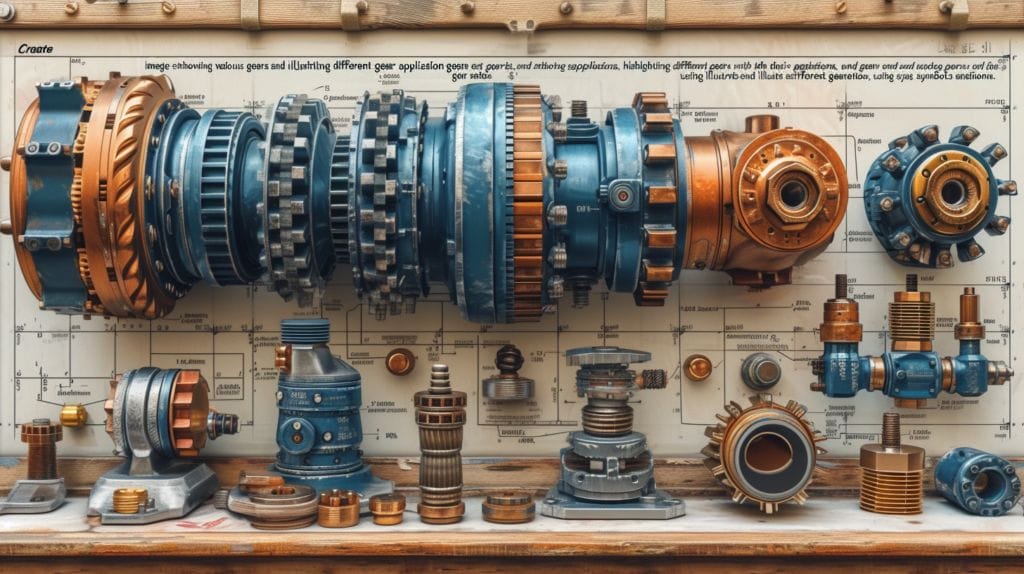
Spur gears, simple and efficient, are often used where large amounts of power need to be transferred, such as in wind turbines and locomotives. Alternatively, another gear like a worm wheel could also be used. Planetary gears, which can be used in a reducer setup, are characterized by their unique arrangement of central and surrounding gears and are frequently found in automatic transmissions in vehicles, offering smooth speed transitions.
Reduction gears, small and compact, are also quintessential in various gear drives, from the simple bicycle to complex industrial machinery, enabling us to control speed and torque effectively. Operating on various axes, reduction gears are central to the operation of various machinery and devices we use daily.
How Do Reduction Gears Work in Construction Tools and Equipment?
Reduction gears in construction tools and equipment work by decreasing the speed of the motor to increase torque, allowing for more power in heavy-duty applications. When using tapcon screws, it’s important to match the drill bit size for tapcon to ensure proper installation and maximum holding strength.
Factors to Consider in Selecting and Designing Reduction Gear
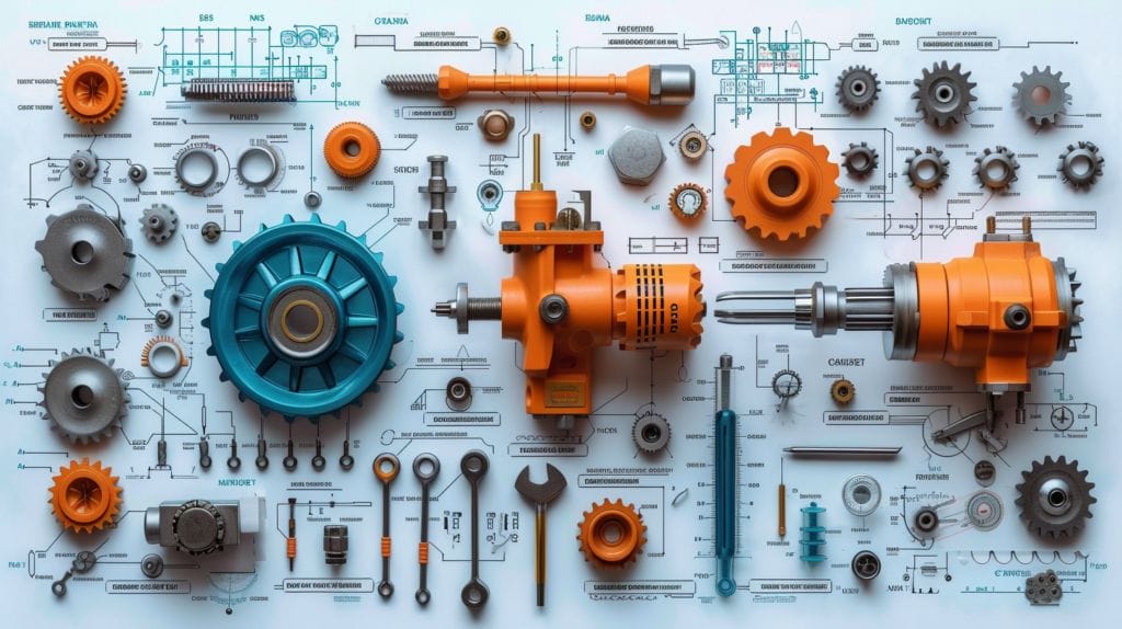
Spur gears, renowned for their simplicity and efficiency, are commonly used in applications where large amounts of power need to be transferred, such as in wind turbines and locomotives. Planetary gears, characterized by their unique arrangement of central and surrounding gears, are frequently found in automatic transmissions in vehicles, offering smooth speed transitions.
Reduction gears are also quintessential in various gear drives, from the simple bicycle to complex industrial machinery, enabling us to control speed and torque effectively. They’re central to the operation of various machinery and devices we use daily.
Conclusion
In wrapping up, we’ve unlocked the fascinating world of reduction gears and learned how gear reduction can multiply the output torque, while reducing the speed. We’ve understood their components, mechanics, and how they generate torque.
We’ve also explored their types and applications, and what to consider in selecting and designing them.
This knowledge can help us appreciate the crucial role that these gears play in our everyday machines, and potentially inspire us in our own mechanical designs.
Frequently Asked Questions
What are reduction gears and how do they work?
Reduction gears work by using a series of gearsets to reduce the rotational speed and increase the torque of a motor’s output. This is achieved by employing gear ratios and gear trains to achieve the desired reduction in speed or increase in torque.
What is gear reduction and why is it important?
Gear reduction, which turns a high gear into a smaller output speed, refers to the process of using gears to reduce the speed of the input shaft, while increasing the torque at the output shaft. It is important because it allows for the adaptation of rotational speed and torque to suit specific operational requirements.
What are the main components of reduction gears?
The main components of reduction gears include worm gears, bevel gears, sun gears, ring gears, and planetary gearboxes, which work together to achieve the desired reduction in speed and increase in torque.
How does gear ratio affect reduction gears?
Gear ratio plays a crucial role in determining the speed reduction and torque increase achieved by reduction gears, realizing the powerful functionality where speed can be reduced and torque can be multiplied. By altering the ratio of the number of teeth on the input and output gears, it can significantly impact the overall performance of the gears.
Can reduction gears be used to reduce noise and vibration?
Yes, reduction gears can be designed to operate with low vibration and reduced noise levels. Gear reduction requiring smooth and quiet operation is typically achieved through the use of helical gears, or the use of another gear type such as a worm wheel for varied applications.

